OsprioIO

An OSDP input/output board with nothing proprietary in the way
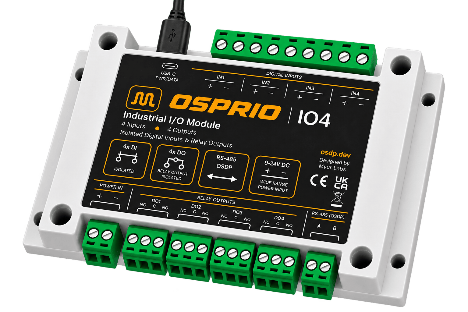
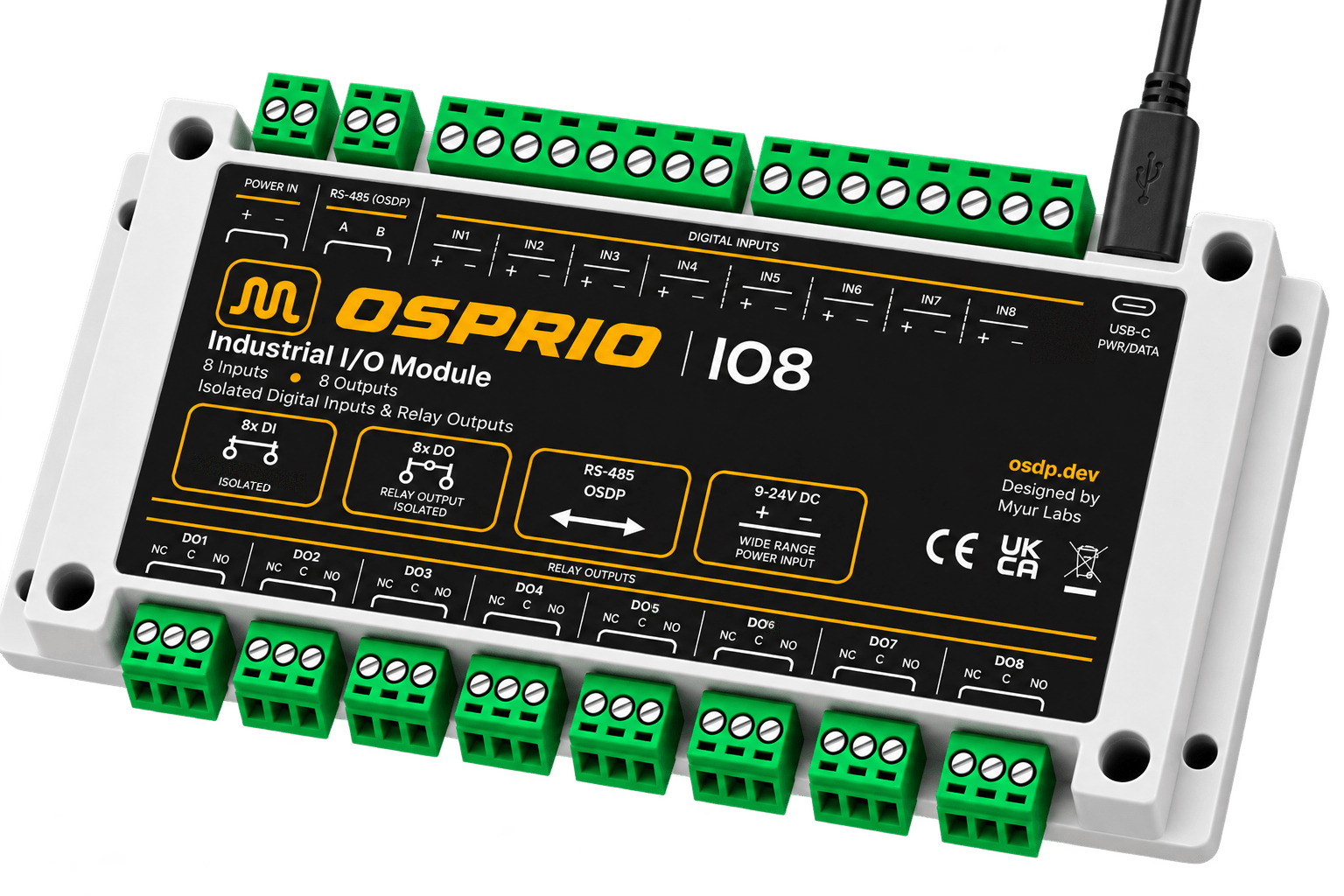
Osprio IO4 industrial I/O module with green screw terminals for four voltage inputs, four relay outputs, RS-485 and power

Osprio IO4 · 4 inputs / 4 relay outputs

Four or eight channels, in and out, pure OSDP

Osprio IO is an OSDP peripheral device with opto-isolated voltage inputs and changeover relays rated for AC or DC loads — four of each on IO4, eight on IO8. Your ACU drives the relays with standard OSDP output commands — on, off, or held for a set time — and each output’s idle state is configurable, so one module handles fail-safe and fail-secure circuits side by side. To commission it, connect your phone to the module’s own WiFi and set the address, baud rate and secure channel key on the page it serves. It then runs as a node on your existing RS-485 bus, with secure channel.

Active Development

Osprio IO runs the same LibOSDP stack we ship in our tooling — so the PD you install behaves like the PD we test against. Explore our integration services →

Platform Highlights

A PD that behaves the way the specification says it should

Most I/O boards treat OSDP as one protocol among several, and it shows on the bus. Osprio IO is OSDP-first: one protocol, implemented properly, with the electrical and mechanical choices a panel installation actually needs.

100% OSDP, no side channel

One protocol, no vendor app and no second channel doing the real work. The PD speaks OSDP over RS-485 to any compliant ACU and reports its capabilities honestly, so everything it does is visible on the bus.

Opto-isolated voltage inputs

The field device applies a voltage across an input’s + and − pins, through an optocoupler, so the logic side never shares a return with your wiring. The PD reports each input to the ACU as contact status.

Relay outputs for AC and DC

Changeover relays bring out NC, C and NO on screw terminals, rated 10 A at 250 VAC or 10 A at 30 VDC. A mains-powered maglock and a 12 V strike wire up the same way, with no interposing relay.

Secure channel, provisioned properly

Full OSDP secure channel with your own SCBK. Enter the key in the portal, or enable install mode so an ACU can open a channel with the default key and write the real one over the bus.

Standalone WiFi configuration

The module raises its own access point and serves the configuration page itself, so a phone is all you carry: no site network, no software to install. Address, baud, key, install mode and output idle states persist across power cycles.

Joins the bus you already have

A standard multi-drop node: give it a free PD address, match the segment’s baud rate, and land A and B alongside the readers already there. Adding I/O costs no new cable run and no second controller.

Field firmware upgrades

Two ways in: upload an image from the module’s own configuration page over WiFi, or send it down the bus as an OSDP file transfer from the ACU. A unit already wired into a panel keeps gaining fixes without leaving the DIN rail.

USB-C or 9–24 V DC

Power from USB-C on the bench and from the panel’s 9–24 V supply in the field, with no jumper to set. The wide-range input runs off whatever rail the installation already has.

Output Control

Fail-safe or fail-secure, decided per output

A door that must unlock when power is lost and a gate that must stay shut are the same command and the opposite wiring. Osprio IO resolves that in configuration rather than in the panel, and the choice is applied as the outputs come up — an output configured fail-safe never pulses through its active state on the way to being ready.

01

Direct activate and deactivate

The ACU turns an output on or off with a standard OSDP output command and the relay follows. Nothing else is needed for a straightforward aux circuit, and nothing else is invented on top of it.

02

Timed operation that means it

Hold an output for a set number of milliseconds and it reverts on its own — a strike release without the ACU having to remember to end it. A timer of zero means indefinitely, exactly as the specification says, not “revert immediately”.

03

Configurable inactive state

Each output carries its own idle level, so the same activate command energises one relay and de-energises another. That is the setting that makes a circuit fail-safe or fail-secure, and it is per output, not per board.

04

Wiring and intent kept separate

How the driver is wired is a property of the board. Which level energises the load is a property of your installation. The two compose cleanly, so a fail-safe door and a fail-secure gate can share one module.

Where It Fits

I/O points wherever the bus already runs

Osprio IO earns its place where a reader-only bus needs contacts and switched loads — without pulling a home run back to the controller for every device.

Door strike and maglock

Timed release from the ACU on a changeover contact, wired fail-safe for a maglock or fail-secure for a strike. Request-to-exit and door position feed back on two inputs.

Gate and barrier

An open pulse and a hold-open output onto a gate operator’s dry-contact input terminals, with loop detector and open-position limit reported as contact status on the same module.

Aux relays and alarm contacts

Lighting, sounders, lift-floor enables and tamper or panic contacts — the odd points that never fit on the reader, brought onto the OSDP bus with the same timed, fail-safe control as a door.

Specifications

Osprio IO at a glance

SpecificationOsprio IO4 / IO8
Protocol
RolePeripheral Device (PD)
PD address0x000x7E, set in portal
Baud rates9600 / 19200 / 38400 / 57600 / 115200 / 230400
Secure channelSCBK, with install-mode osdp_KEYSET provisioning
Output control capability04 — direct, timed, configurable inactive state
Contact status capability01 — unsupervised circuit, default interpretation
Inputs
Channels4 (IO4) or 8 (IO8) × voltage input, opto-isolated
TriggerExternal voltage applied across + / − pins
IsolationOptocoupler, input to logic
ReportingContact status, active / inactive, debounced 30 ms
Outputs
Channels4 (IO4) or 8 (IO8) × relay, NC / C / NO changeover
Contact rating10 A @ 250 VAC · 10 A @ 30 VDC
IsolationOptocoupler drive, relay contact isolated from logic
Inactive statePer output, persisted — fail-safe or fail-secure
Power and interfaces
Power inputUSB-C, or external 9–24 V DC
BusRS-485, A / B screw terminal
ConfigurationOnboard WiFi configuration portal
Firmware updateWiFi config portal, or OSDP file transfer from the ACU
Mechanical
EnclosureIndustrial ABS, suitable for DIN mounting
TerminalsPluggable screw terminals throughout
MarkingsCE · UKCA · WEEE
FAQ

We get these questions a lot

Are the inputs supervised with end-of-line resistors?

No, and we would rather say so plainly. The inputs are opto-isolated voltage inputs — the field device applies a voltage across the pins to trigger one — and the module reports them to the ACU as unsupervised contact status. End-of-line supervision needs sensing this hardware does not have, so we do not claim it. The capability levels the module advertises are listed in the specifications.

What can an ACU actually do with the outputs?

Everything a door, gate or aux circuit needs, using standard OSDP output commands: switch an output on, switch it off, or hold it for a set time and let it revert on its own. Each output also carries its own idle state, which is what lets one module drive a fail-safe maglock and a fail-secure strike side by side.

Can I set the secure channel key (SCBK) without a laptop on site?

Yes. Enter your key in the WiFi configuration portal before installation, or enable install mode and let your ACU write the key over the bus during commissioning. The two are mutually exclusive and the board refuses the combination rather than silently picking one.

Is install mode safe to leave on?

No. Install mode lets a channel open with the published default key, so anyone on that bus can read the exchange. Use it on a one-to-one connection to provision the real SCBK, then turn it off. The portal says the same thing at the point of decision.

Can it run from the panel supply instead of USB-C?

Yes — a wide-range 9–24 V DC input sits on the power-in terminal. USB-C is there for the bench and for configuration, not as the only way to power the module.

How do I get firmware updates onto an installed module?

Two ways, and neither takes the module off the rail. Connect to its WiFi and upload the image from the configuration page, or push it down the bus as an OSDP file transfer from the ACU. The flash carries two application slots, so the running firmware stays intact while the new image is written and the module switches over on reboot.

Will it work with an ACU that isn't ours?

That is the point of building it OSDP-first. Osprio IO advertises its capabilities the way the specification defines them, so any compliant ACU discovers every input and output on the board and drives them without a vendor-specific integration.

Have a question? Ask us →

Early access

Join the Osprio IO waitlist.

Osprio IO is in active development and not yet shipping. Join the list for milestone updates, early-access details, and first word on pricing and availability for IO4 and IO8.